Join to our channels: new products, coupons, best deals:
Flight controllers
Matek H743-SLIM
Multirotors → FPV Racing drones → Flight controllers → H7 FCs → Matek H743-SLIM
| MCU: | H743 |
| Gyro: | ICM20602 & MPU6000 |
| Barometer: | DPS310 |
| OSD: | + |
| CAM in: | 2 |
| Power : | 2-8S |
| 3.3V BEC: | 0.2A |
| 5V BEC: | 2A |
| Current Sensor: | - |
| PWM: | 13 |
| ESC type: | - |
| ESC: | - |
| BLHeli: | - |
| Receiver: | - |
| RSSI: | + |
| VTX: | - |
| UART Rx: | 7 |
| UART Tx: | 7 |
| I2C: | 2 |
| CAN: | 1 |
| Buzzer pad: | + |
| LED pad: | + |
| Vbat: | 2 |
| CURR pad: | 2 |
| Air speed: | + |
| IR/INR pad: | + |
| Blackbox: | MicroSD |
| USB: | Type-C |
| USB pads: | + |
| DJI compatible: | + |
| Bluetooth: | - |
| Size: | 36x36x5mm |
| Mount Holes: | 30.5x30.5mm |
| Weight: | 7g |
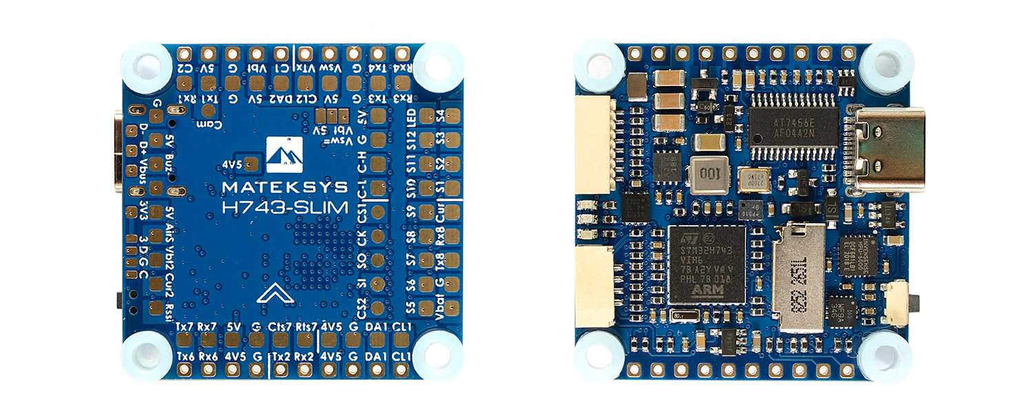
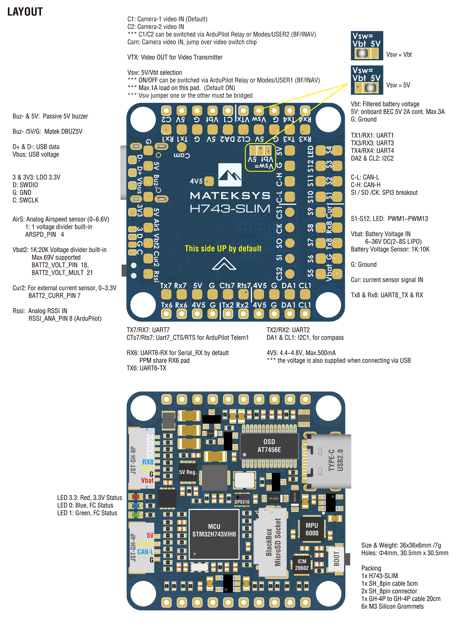
Flight Controller H743-SLIM
STM32H743VI, ICM20602 & MPU6000, DPS310, OSD, 7x UARTs, 2x I2C, 1xCAN, 13x PWM outputs, BEC5V,

Gallery
Specifications
Layout
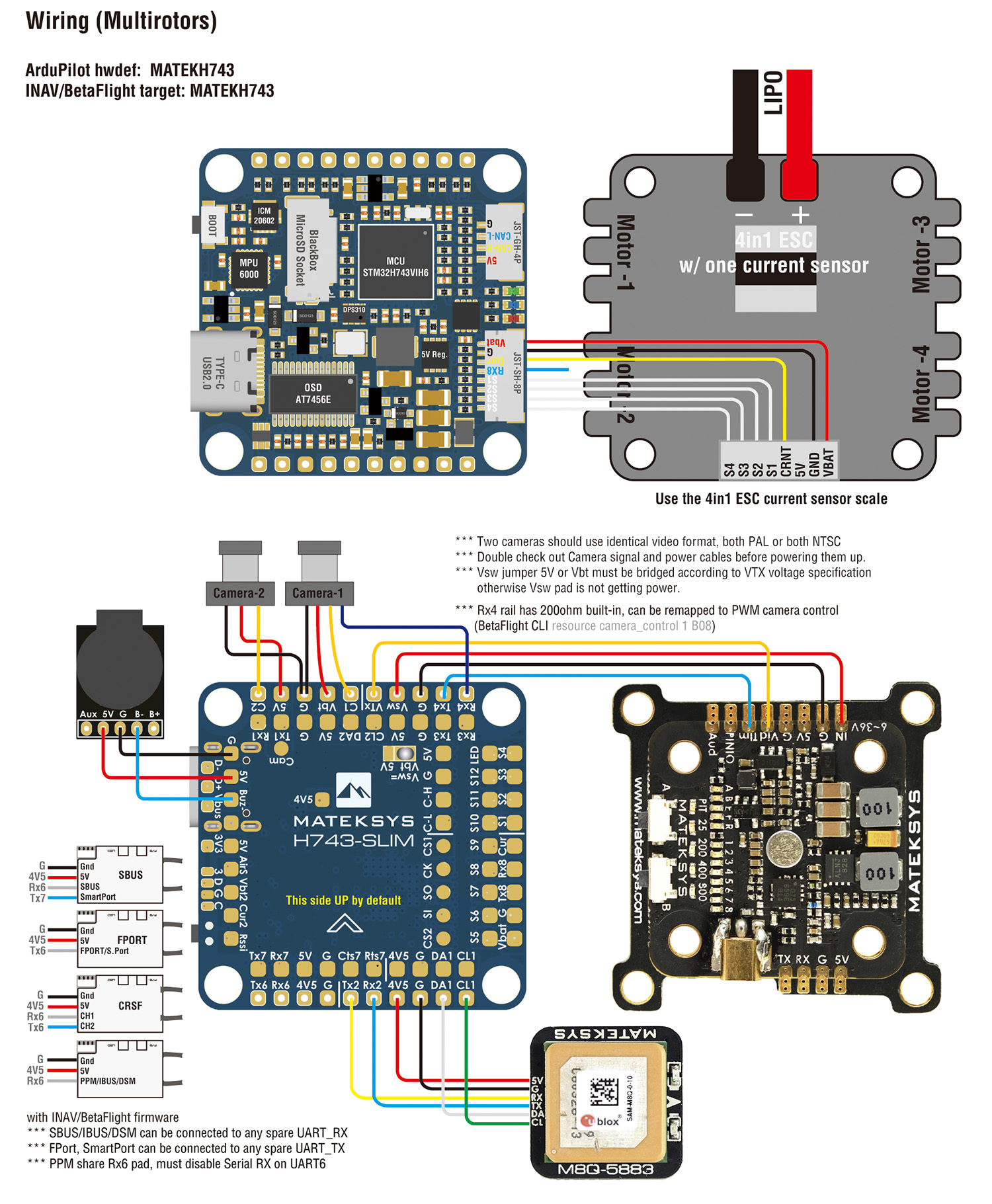
Wiring
ArduPilot mapping
ArduPilot Relay
reserved
Tips
Resellers
Share
Prices for Matek H743-SLIM in stores
Deals found: 32 (Banggood1)
| Store | Stock level | Lot price | Shipping cost | Coupon / promocode | Pcs./lot | 1pc price |
| Banggood | Out of stock | $80 | 1 | $80 |
See also

Mateksys CANPDB-4A BEC & JST-GH Splitter
$17

Matek H743-SLIM - super light support for Dart250g

Join to our channels: new products, coupons, best deals: